DAI - Installation - Model6381/F Installation Manual

Please follow all instructions carefully when installing this module
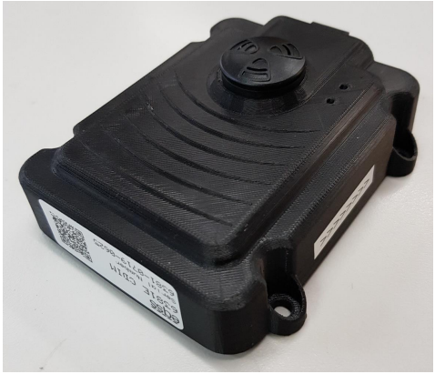
Installation
Determine Mounting Angle
The Stability Sensor must be mounted with the arrow pointing down towards the
ground.
The Stability Sensor is mounted using four M6 x 12 bolts.
Wiring Connections
A loom connects the Model6381F to a power source and the cutouts.
The table below lists the wire pin outs for the connection cable.
Operation
The Stability Sensor has 3 operating modes; Normal, Warning and Alarm.
Normal Mode
The Stability Sensor is in normal mode when the angle is below the warning threshold, relative to the reference angle. The buzzer does not sound in this mode. Both the Alarm
& Warning outputs are producing a VCC signal. The vehicle is in a safe condition and
can be operated as normal.
Warning Mode
In this mode the angle is above the warning threshold, but below the alarm threshold.
The buzzer produces an intermittent tone. The frequency of the tone increases as the
angle approaches the alarm threshold. The Warning output is open/floating and Alarm
output is producing a VCC signal. This indicates the vehicle is approaching a dangerous
angle and needs to be corrected.
Alarm Mode
In this mode the angle has passed the alarm threshold. The buzzer produces a solid
tone. Both the Warning & Alarm outputs are open/floating. The vehicle is beyond a
dangerous angle and must be immediately corrected.
Pre Operation Checks after power on, the buzzer will produce a beep, even though it is below the warning/alarm
threshold. This is normal and indicates that the Stability Sensor is active and has
completed its self test.
Calibration
In order to perform administrative tasks such as calibration and monitoring the real time
inclinometer data, the unit provides a wifi access point to a web interface that can be accessed via
the web browser on your phone or laptop.
The SSID of the wifi access point is: model6381_prototype
The password is: aaaabbbbcccc
(4 a's, 4 b's, 4 c's)
Open an internet brower (chrome or firefox for example) and type this URL into the address bar:
192.168.4.1
You should see the following page:
Tap “Calibration” to open the calibration page.
To perform a calibration, first ensure that the EWP chassis is parked such that it is level in both
axes, as this calibration procedure will zero the pitch and roll internal inclinometers. When this is
done, tap “Calibrate Chassis Angle”. The chassis pitch and roll should both then read 0.
The warning mode occurs between 5 degrees and 7 degrees. The alarm mode occurs for any angle
above 7 degrees. Clicking on “Edit Settings” will open a page that will allow the modification of
these parameters.
Settings
Clicking on “Edit Settings” in the calibration page will open the settings page. The warning and
limit angles may be modified along with other parameters.
After changing a parameter on this page, click its corresponding “Set” button to save this setting

If the unit is mounted at an angle that is off by more than 60
degrees from the direction of the arrow on either axes the
stability sensor will not function correctly.
When replacing the cover ensure nothing obstructs the seal
(such as the buzzer wires) and securely fasten the bolts to the
base of the enclosure. Failure to do so will compromise the
seal, allowing moisture ingression that will damage the unit.
Related Articles
Gen3 - Attachments - Change Between Automatic & Manual Tool Selection
Changing settings via the display was added in Display Version 1129. Check the current display version in the Status Menu. If the version is older then follow the instructions here to update the display. Press Enter on the user control dial to enter ...DAI - Installation - Model6381/C Installation Manual
Please follow all instructions carefully when installing this module Installation Determine Mounting Angle The Stability Sensor must be mounted with the arrow pointing down towards the ground. Mounting the Unit The Stability Sensor is mounted using ...DAI - General - What is Dual Axis Inclinometer?
The Model6381 Dual Axis Inclinometer is a multi functional sensor / system used for determination of relative angles with respect to gravity. The system is suitable for use as stand alone warning system in applications, such as, chassis level and man ...Gen3 - Installation - Pressure Sensors MUST be mounted exactly as Installation Manual shows
Pressure Sensors MUST be mounted exactly as the Installation Manual shows in illustrations The various pressure sensors that the EQSS relies on to monitor shifting hydraulic pressures are mounted to the key telehandler (on boom) hydraulic blocks. ...Gen3 - Installation - Manitou MT1840 2021 Model Connection Schematics
Manitou MT1440/MT1840 2021 Model Connection Schematics What's different from earlier Manitou models? The 2021 model uses an internal CAN bus and thus the EQSS Gen 3 uses a CAN I/O module to extract information about drive direction and stabilisers ...