Gen1 - Installation Deici Icarus 40.17 Gen 1 to Gen 3 - CPIM Module Installation

The CPIM is responsible for processing the information sent from the pressure sensors
and also measures the carrier attitude
The CPIM should be mounted in the same location as the GEN1 ISM modules.
Below: Remove GEN1 ISM Modules and Install GEN3 CPIM Module
The CPIM must be mounted with the 5x M12 screw lock connectors pointing down and
must not be off by more than 5 degrees on both axes in order to correctly measure the
carrier attitude.
Once the CPIM has been mounted the cables from the external sensors can be
connected. There are six connectors in total on the CPIM as shown in the picture below.
Below: CPIM Connector Descriptions
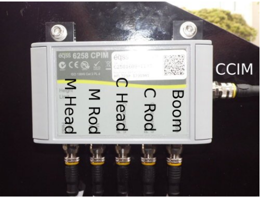
The four on the bottom left are for the pressure sensors, connect to the pressure sensor
cables (according to the labels).
The two connectors on the side of the housing and on the bottom far right are for the CAN
bus interconnections. The boom cable is connected to the bottom far right connector. The
connection on the right is used to connect to the CPIM to CCIM on the CAN bus. This is
the CCIM cable.
Coil up any additional cable from the pressure sensors, light tower and boom cable and
store underneath the covers along the chassis.
The CCIM cable will be connected into the CCIM module.

Do not plug the pressure sensor cables into any of the CAN
connectors and vice-versa. This will damage the system.
Related Articles
Gen1 - Installation Deici Icarus 40.17 Gen 1 to Gen 3 - CCIM Module
The CCIM connects the system into the machine electronics and interfaces between the display and the external sensors The CCIM along with the backup battery should be mounted inside the dashboard near the rest of the machine electronics. The CCIM and ...Gen3 - Installation - Can Pressure Input Module (CPIM)
The CPIM is responsible for processing the information sent from the pressure sensors and also measures the carrier attitude (telehandler chassis angles). The CPIM is mounted on the chassis and must be mounted with the five M12 screw lock connectors ...Gen1 - Installation Deici Icarus 40.17 Gen 1 to Gen 3 - Pressure Sensor Installation
The hydraulic pressure sensors are used to measure the lifting load of the telehandler. There are two pressure sensors that need to be mounted to measure the pressure in the main lift cylinder. The pressure sensors from the GEN1 will need to be ...Gen1 - Installation Deici Icarus 40.17 Gen 1 to Gen 3 - Cable Reeler Installation
The cable reeler contains the sensors required to measure the boom extension and boom angle to allow the Gen3 LMS to calculate the boom position. The GEN3 and GEN1 cable reelers are mechanically identical and can be directly swapped over. Use the ...Gen3_ITC - Installation - Volvo L120H & L90 CPIM Installation
The CPIM is responsible for processing the information sent from the pressure sensors, the articulation sensor and the RFID sensor. The CPIM also measures the chassis pitch and roll with its internal angle sensors. Installation Steps: 1. Drill two M8 ...